Visualizing element fields using surfaces
Surfaces are graphical representations that can be used to represent two or three dimensional elements in CMGUI. Surfaces can be used to represent the faces of a 3D element or mesh, for example.
Surfaces and are created as graphics in the scene editor. To create a very simple surface graphic, go to the File menu, select Read, then Node file. Read in cube.exnode from the example a2 directory. Then using the Read and Elements file menu options, read in cube.exelem from the same directory. If you now create a graphics window, you will see a simple cube rendered in the default lines graphic. Open the scene editor window by selecting it from the Graphics menu. Select the cube scene object, then in the graphics panel select surfaces in the drop-down menu. Click the Add button to the right of this menu. A new graphical setting will appear in the list, below the lines graphical setting. In the 3D window, your cube will now be rendered with white shaded surfaces.
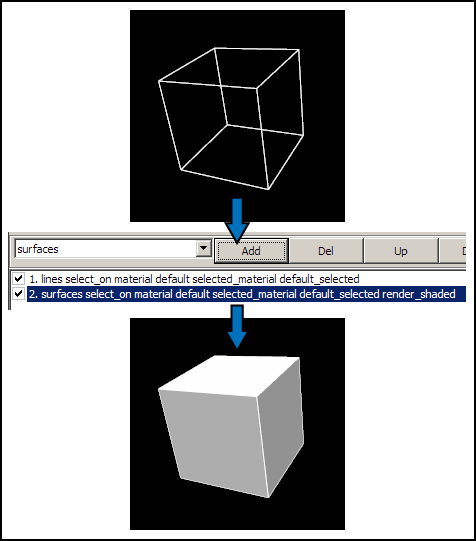
Figure 1: Adding surfaces to a mesh Using the example a2 cube, adding a surface graphical setting creates a basic surface in the default material (white).
The tessellation setting of the surface graphical setting determines the detail level of surfaces. Each face in a surface graphical setting is divided into a number of squares (each made up of two triangles) determined by the tessellation. The discretization can be independently set for each of the three coordinate dimensions, allowing you to set different detail levels for different parts of surface.