Visualizing element fields using lines and cylinders
Lines and cylinders are graphical representations which can be used to visualize 1-D elements in CMGUI - including line elements at the edges of 2-D faces or 3-D elements. From Cmgui v3.0, cylinders are just a variant of lines specified by changing the Line shape to 'circle extrusion' combined with line scaling options; in previous versions of Cmgui, cylinders were a separate graphics type.
In general, lines are used to visualize the basic shape of a mesh. Note in very old versions of Cmgui lines were automatically created when region 'groups' were read from file, but this is no longer the case: all graphics must be intentionally created by the user (see the scene editor).
If you wish to create lines in the graphics window, you first need to read a model containing line elements. As an example go to the file menu in CMGUI and select Read, then Node file. Read in cube.exnode from the example a2 directory. Then using the Read and Elements file menu options, read in cube.exelem from the same directory. Select the Graphics Scene Editor menu item and select the region you wish to create graphics for from the list at the left; in the example it is the root region "/". Click on add and select lines. A default coordinate field will automatically be chosen, which is the minimum needed for lines graphics. If you now create a graphics window (using the Graphics menu item 3-D window) you will see this cube rendered in 1 pixel thick lines using the default (white) material.
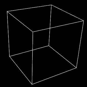
Figure 1: The lines graphics created for a cube mesh. This mesh was created by reading the cube.exnode and cube.exelem files from example a2. Note that the example a2 com file creates cylinders to visualize the cube mesh.
Settings for lines
The tessellation option in the scene editor controls the number of line segments used along the line element to approximate a curve or control visualisation of the data field along it. With 'circle extrusion' line shape (cylinders) the Circle Divisions option on the tessellation controls the number of line segments around the cylinder with higher numbers better approximating a circle. (Prior to Cmgui v3.0 Cylinder graphics had a Circle discretization value for this purpose.) (Figure 2).
Lines have relatively few settings for altering their appearance (Figure 2). The following settings are available for lines:
- Coordinate field: When you check this box, you are able to select the coordinate field that the lines are drawn according to. This is used any time the coordinate field used for the lines needs to differ from the default coordinate field used for the whole graphical element (in the general settings).
- Exterior: When this check box is selected, the lines will only be drawn on the exterior faces of a 3D mesh, or the outside edges of a 2D mesh. This can be useful with large, complex meshes.
- Face: Checking this box allows you to select which face of 3D elements is visualized by lines. Faces are selected according to one of the 3 xi directions of the element, and it's value (either 0 or 1).
- Select mode: This drop-down menu allows you to select different selection behaviours for the lines.
- select_on - The default setting; line elements are able to be selected and selected elements are highlighted by rendering in the selected material.
- no_select - No selection or highlighting of line elements.
- draw_selected - only selected lines are drawn.
- draw_unselected - only unselected lines are drawn.
- Material: This drop down menu allows you to select which material the lines will be rendered as. Materials are defined in the material editor window. Note: the material for lines is unshaded. This means that lines only use the diffuse colour for the selected material to draw the lines.
- Line width: You can enter a value in this box to set the thickness of the lines in pixels. This width is independent of zoom, and remains constant through any transformation. Setting this value to 0 results in lines of 1 pixel wide (the default).
- Data: This setting allows you to choose a field which is used to colour the lines according to a spectrum. Use the Spectrum drop-down menu to choose from one of the spectra defined in the spectrum editor window.
- Selected material: Use this drop-down menu to select which material will be used to render selected lines.
In addition to these settings there is a command line setting that can be very useful when using line based visualizations: gfx modify window 1 set perturb_lines. This command helps to prevent the "dotted lines" effect that occurs when lines and surfaces interfere.
Note: if no lines appear, you may not have added faces (and lines) to the mesh - try the gfx define faces command.
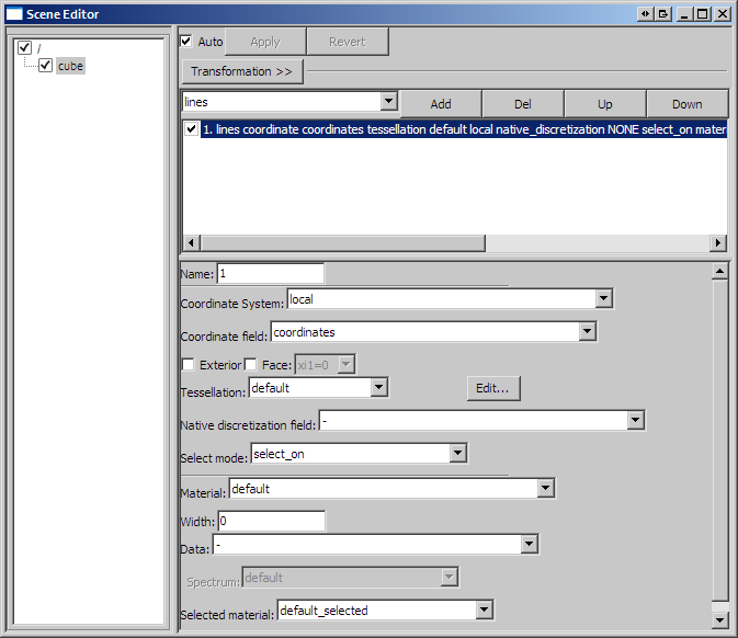
Figure 2: The scene editor settings available for a lines graphical setting.
Settings for cylinders
Since Cmgui v3.0 cylinders are just lines using additional 'line shape' options shared with streamlines graphics, currently restricted to 'line' or 'circle extrusion' with equal scaling in all lateral directions. Note when choosing a line shape other than the default 'line', the resulting graphics scale with the model as you zoom in, whereas 'line' shape gives constant thickness in screen space.
Options controlling the visualisation with 'circle extrusion' line shape:
- Line base size: This is the base diameter of the cylinders in units of the current graphics coordinate system; scaling by field with scale factors is added to this value. It currently has 2 values which are constrained to be equal, anticipating future use. Beware that prior to Cmgui v3.0 the equivalent option was the 'Constant radius'.
- Line scale field: This drop-down menu allows you to select a scalar field to scale the diameter of the cylinders across the model according to this field. A good example of this is shown in example a4. Beware that prior to Cmgui v3.0 the equivalent option was the 'scalar radius' field'.
- Line scale factors This box allows you to enter two values as factors for the scaling the 'line scale field' lateral to the line, but note that they are currently restricted to being equal-valued. (In future, different scaling in each lateral direction is anticipated, for use with multi-component 'line scale fields'). Important: use a value of "2*2" if the line scale field is a radius.